Topology Designer

Overview

The MIMIC Topology Designer is a visual editor for building, modifying, and visualizing large network topologies. Unlike the older Enhanced Topology Wizard which is a step-by-step dialog, the Designer presents the entire topology as an interactive canvas. You can add and remove devices, wire up interfaces, group devices into nested submaps, lay out the graph automatically, replicate the topology with new IPs, and save the result as a standard MIMIC agent configuration (.cfg) file.

The Designer is well-suited for:

  • Building or editing complex multi-level networks from scratch.
  • Importing an existing .cfg file and visually verifying or modifying it.
  • Merging two topologies and resolving the resulting agent ID and IP space.
  • Replicating a small topology many times with fresh IP subnets per copy.
  • Organizing very large topologies into collapsible submaps so the canvas remains readable.
  • Generating an initial star topology with the built-in Auto Topology Wizard.

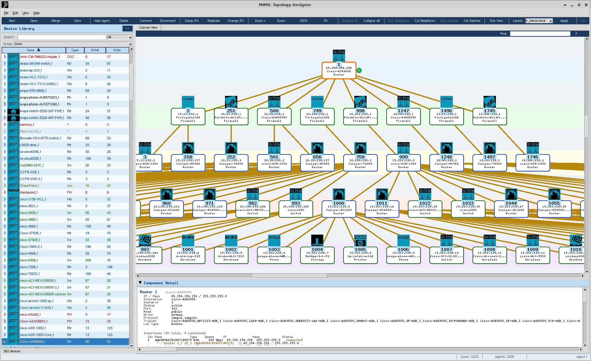
Figure 1: Topology Designer Main Window

Figure 1: The Topology Designer main window with a sample topology, Device Library panel on the left, main canvas in the center, and Component Detail panel at the bottom.

Launching the Designer

The Designer is launched from inside MIMICView:

  • From the menu bar, select Topology > Designer...

The Designer runs as a separate process from MIMICView, so the rest of MIMICView remains responsive while you work in the Designer.

Only one Designer instance can run at a time. If you select Topology > Designer... while a Designer is already open, MIMICView raises the existing window to the front instead of starting a second copy.

Note: the Designer must be launched from a MIMIC install directory (so it can find the MIMIC bundled Tcl/Tk and helper libraries). If you try to run the script directly with a third-party wish, the Designer displays an error dialog asking you to launch it from MIMIC.

The Main Window

The Designer window is divided into the following areas:

  • Menu bar — File, Edit, View, Help. Every command in the Designer is available from a menu.
  • Toolbar — Buttons for the most common operations: New, Open, Save, Add Agent, Connect Interface, zoom, layout, and more.
  • Device Library (left panel) — A searchable, filterable tree of every simulation available on this MIMIC install. Drag a device onto the canvas to instantiate it as a new agent.
  • Canvas (center) — The main drawing area where agents and submaps are displayed and edited.
  • Tree View (optional, hidden by default) — A textual tree of all agents and their interfaces. Useful for navigating very large topologies.
  • Component Detail (bottom, collapsible) — Shows the properties of the currently selected agent, interface, or connection.
  • Status bar — Operation status, current zoom percentage, agent count, and current selection summary.

Each panel can be folded or unfolded with the small triangle / arrow button on its title bar. The Designer remembers the last fold state and the last panel widths from one session to the next.

Menu Bar

File

  • New (Ctrl+N) — Discard the current topology and start with an empty canvas.
  • Open... (Ctrl+O) — Load a .cfg file. If a sibling .lay (layout) or .map (submaps) file exists next to the .cfg, both are loaded automatically. If the canvas already contains agents, a small dialog asks how to load the new file:
    • Replace... — Wipe the current canvas and load the new file fresh. If you have unsaved changes you will first be offered the chance to save them.
    • Merge... — Keep the current topology and append the file's agents and connections. The new agents' IDs are offset past the highest existing ID; _TOPO_ references are remapped automatically. The new block is placed in its own space (to the right for top-down hierarchical, circular, star, and force layouts; below for LR hierarchical and grid) so it doesn't overlap the existing topology. If any IP in the merged file is already used, the merge is refused with an explanatory error and the canvas is left untouched.
    • Cancel — Do nothing.
    An empty canvas skips the chooser and loads directly. Open Merge can be undone with Ctrl+Z.
  • Merge... — Merge agents from other config files into the canvas. The behavior depends on what is already on the canvas:
    • Empty canvas: opens the two-file picker directly. Choose two .cfg files; their combined topology becomes the new canvas.
    • Non-empty canvas: a small dialog asks how to merge, mirroring the three-way Open... chooser:
      • Replace... — Wipe the current canvas, then open the two-file picker to merge two .cfg files into it. (This is the historical Merge behavior.)
      • Merge... — Keep the current topology and append one additional .cfg file after the highest existing agent ID. Same machinery as Open...'s Merge: IDs are offset, IP conflicts pre-flight, the new block lands on the layout's cross-flow axis, and the action is undoable with Ctrl+Z.
      • Cancel — Do nothing.
  • Save (Ctrl+S) — Write the current topology as a .cfg file, together with a sibling .lay file storing per-agent canvas positions and a sibling .map file if you have created any submaps. The first save prompts for a file name; subsequent saves overwrite.
  • Save As... — Save to a user-chosen path.
  • Exit (Ctrl+Q) — Close the Designer.

Edit

  • Undo (Ctrl+Z) / Redo (Ctrl+Y) — Reverse or re-apply the last topology-changing operation. The Designer keeps up to 20 undo levels. View changes such as zoom, pan, and expand/collapse are not undoable.
  • Add Agent — Add one or more new agents. See Adding Agents.
  • Delete Agent (Delete) — Delete the selected agent(s). Any connections to deleted agents are removed automatically.
  • Connect Interface / Disconnect Interface — Wire up or break a link between two interfaces. See Connecting Interfaces.
  • Select > submenu:
    • All — Select every agent on the canvas.
    • None — Clear the selection.
    • Invert — Toggle the selected state of every agent.
    • By Number... — Select agents by numeric ID range, for example 1-5, 42, 100-200.
    • By IP... — Select agents by IP address or subnet.
  • Replicate Topology — Create multiple copies of the current topology with remapped IPs. See Replicate Topology.
  • Change IPs — Bulk-remap IPs across detected /24 subnets. See Change IPs.
  • Dump IPs — Export host and used IPs as text. See Dump IPs.
  • Auto Topology Wizard... — Open the multi-step wizard that generates a star or multi-level topology. See Auto Topology Wizard.
  • Group Selection into Submap... — Group the currently selected agents into a new submap. Requires at least two selected agents.
  • New Submap... — Create a new submap from scratch.

View

  • Zoom In (Ctrl+=) / Zoom Out (Ctrl+-) / Reset Zoom (Ctrl+0) — Standard zoom controls. Zoom range is 0.1x to 4.0x.
  • Fit in Window (Ctrl+F) — Compute a zoom and pan such that all visible nodes fit in the canvas. Zoom is capped at 1.0x so small topologies are not over-magnified.
  • Expand All / Collapse All — Show or hide every non-root agent. The expanded states of every submap are snapshotted before Collapse All so Expand All restores them.
  • Expand Neighbors / Collapse Neighbors — Show or hide the immediate peers of the selected agent(s).
  • Expand Subtree / Collapse Subtree — Show or hide the full downstream tree (BFS) of the selected agent(s).
  • Expand All Submaps / Collapse All Submaps — Bulk open or close every submap icon.
  • Submap Manager... — Open a modal list of every submap with Edit / Delete / New buttons. See Submaps.
  • Canvas Layout > submenu — Apply an automatic layout. See Canvas Layouts.
  • Tree View — Toggle the textual agent / interface tree panel.
  • Device Library (Ctrl+D) — Fold or unfold the Device Library panel.

Help

  • Usage — Open the in-app usage guide (a tabbed reference of zoom, file, library, connection, IP, and submap operations).
  • About — Display the Designer version and build timestamp.

Toolbar

The toolbar duplicates the most frequent menu commands. Hover over any button to see its tooltip in the status bar. From left to right:

  • File group: New, Open, Merge, Save.
  • Edit group: Add Agent, Delete, Connect, Disconnect.
  • IP group: Dump IPs, Replicate, Change IPs.
  • Zoom group: Zoom +, Zoom -, 100%, Fit in Window.
  • Visibility group: Expand All, Collapse All, Expand Neighbors, Collapse Neighbors, Expand Subtree, Collapse Subtree.
  • Tree View toggle.
  • Layout: combobox (grid, hierarchical, lr_hierarchical, circular, star, force, spring) + Apply button.
  • Auto Topo — Open the Auto Topology Wizard.
  • Devices — Toggle the Device Library panel.
Tip: If the Designer window is too narrow to show every button, the rightmost buttons collapse into an overflow >> menu so nothing is ever hidden behind the window edge.

The Canvas

The canvas is the main drawing area. Each agent is drawn as a rounded rectangle, color-coded by device type, and labeled with its agent ID and host IP. Connections between interfaces are drawn as lines with arrowheads showing which end is the source. Submaps are drawn as larger, boldly-outlined icons with the submap name and a member count.

Pan and Zoom

  • Mouse wheel — Zoom in or out at the cursor location.
  • Middle-click + drag, or Ctrl + drag — Pan the canvas.
  • Scrollbars on the right and bottom let you pan with the mouse.
  • Ctrl+0 — Reset zoom to 100%.
  • Ctrl+F — Fit all visible nodes in the current window.

Selection

  • Left-click an agent — Select that agent only.
  • Shift + left-click — Add or remove an agent from the current selection.
  • Left-click + drag on empty canvas — Rubber-band selection. Every agent inside the rectangle becomes selected. Hold Shift to add to the existing selection.
  • Left-click on empty canvas — Clear the selection.
  • Escape — Clear the selection.

Moving Agents

  • Left-click + drag on an agent — Move the agent to a new position. The new position is saved and is preserved when you save the topology.
  • Drag an agent onto a submap icon — Add the agent to that submap. If the agent is already a member of another submap, the Designer asks for confirmation before moving it.

Editing

  • Double-click an agent — Open the Edit Agent dialog.
  • Double-click a submap icon — Expand or collapse the submap.
  • Right-click anywhere — Open a context menu appropriate to what was clicked. See Right-Click Context Menus.

Inline Badges on Agent Nodes

Two small icons can appear on or beside an agent node. They are passive visual cues that let you act on a single agent without first hunting through menus.

Green + badge — Quick Connect

A small green circle with a white + appears just to the right of an agent node whenever that agent is the only selected agent on the canvas (so it does not clutter multi-selections). Clicking the + enters Quick Connect mode:

  1. The cursor changes to a crosshair.
  2. An orange dashed rubber-band line follows your mouse, anchored at the selected agent.
  3. Click on a second agent — the Connect Interface dialog opens with both ends pre-populated, so you only need to choose the source and target interfaces and confirm.
  4. Press Escape at any time, or click on empty canvas, to cancel and exit Quick Connect mode without creating a link.
Tip: Quick Connect is the fastest way to wire two specific agents. It is equivalent to selecting the source, invoking Edit > Connect Interface, and picking the target from the dropdown — but it lets you point at the target visually instead of looking it up by ID.

If you drag the rubber-band line near a viewport edge, the canvas auto-scrolls smoothly toward that edge so you can reach a target agent that is currently off-screen. Move the cursor back inside the viewport to stop scrolling.

Orange >> badge — Hidden Neighbors

A small orange oval with white >> in the bottom-right corner of an agent node means that the agent is connected to at least one peer that is currently hidden from the canvas — typically because the peer was collapsed by Collapse Subtree, Collapse Neighbors, Collapse All, or because the peer lives inside a collapsed submap.

The badge is a hint, not a button: it tells you the agent has off-canvas relationships you cannot see right now. To reveal them:

  • Select the agent and choose View > Expand Neighbors (or the Exp Neighbors toolbar button) to bring the immediate peers back onto the canvas.
  • Use View > Expand Subtree to reveal the full downstream tree.
  • If the hidden peer is inside a submap, expand that submap (double-click its icon or use View > Expand All Submaps).

The badge disappears as soon as every connected peer is visible again.

Note: the + badge and the >> badge are deliberately placed on opposite sides of the node (right edge vs. bottom-right corner) so they never overlap. The same >> glyph is reused for the toolbar overflow indicator (when the window is too narrow to show every toolbar button) — context tells you which one you are looking at.

Device Library

The Device Library panel (left side of the window) shows every simulation installed on this MIMIC system. Each row identifies a simulation by name, device type (Router, Switch, Firewall, Linux, Windows, etc.), Ethernet interface count, and MIB count.

Filtering and Grouping

  • Search — Type any substring in the search box. Matching is live and case-insensitive, and runs across the simulation name, device type, vendor, MIB list, and system description.
  • Type dropdown — Restrict to a single device type, or show all.
  • Group by dropdown — Reorganize the tree by type, vendor, mib, iftype, or none (flat list).
  • Sort indicator — Click the Name column header to sort A↔Z or Z↔A.

Adding Agents from the Library

  • Drag a device onto the canvas — Open the Add Agent dialog pre-populated with that device's simulation, scenario, and interface set. The dropped position becomes the agent's initial canvas position.
  • Click a device, then use Add Agent — The selected device pre-fills the Add Agent dialog.

Folding the Panel

Click the small arrow on the panel header (« when unfolded, » when folded) or press Ctrl+D to fold the Device Library to a thin strip and reclaim canvas space. The Designer remembers the panel width across sessions.

Note: the Device Library is loaded asynchronously after the Designer starts so the window appears quickly. While loading you may see a "Loading device library..." indicator; you can still work in the Designer in the meantime.

Tree View

The Tree View is an optional textual representation of the topology, useful for navigating very large topologies where the canvas alone becomes cluttered. Toggle it from View > Tree View or the toolbar button.

When open, the panel is split in two:

  • Left side — A tree of all submaps (if any) and all agents. Each agent row expands to show its interfaces.
  • Right side — Properties of the currently selected agent (hostaddr, mask, port, communities, simulation, etc.) and the list of its connections.

Selecting an agent in the Tree View also selects it on the canvas, and vice versa. Double-clicking an agent opens the Edit Agent dialog. Right-clicking any row opens the same context menu as right-clicking the agent on the canvas.

Interface lists are paginated for performance. If an agent has many interfaces, the first 10 are shown immediately and an additional "More (N more — double-click to load)" row appears at the bottom. Double-click it to load the next batch.

Component Detail

The Component Detail panel at the bottom of the window shows the full set of properties for whatever is currently selected:

  • An agent — hostaddr, mask, port, read / write communities, protocol, simulation, scenario, triplet, private directory, device type, and status.
  • An interface — ifIndex, ifName, ifType, IP, mask, link state, and (if connected) the peer agent and interface.
  • A connection — both ends of the link, including IP addresses at each end.

Click the small triangle on the panel header to fold it down and reclaim vertical space.

Adding Agents

There are several ways to add an agent:

  • From the menu: Edit > Add Agent.
  • From the toolbar: click the Add Agent button.
  • From the canvas: right-click an empty area and choose Add Agent Here. The new agent is placed at the click location.
  • From the Device Library: drag a device onto the canvas.

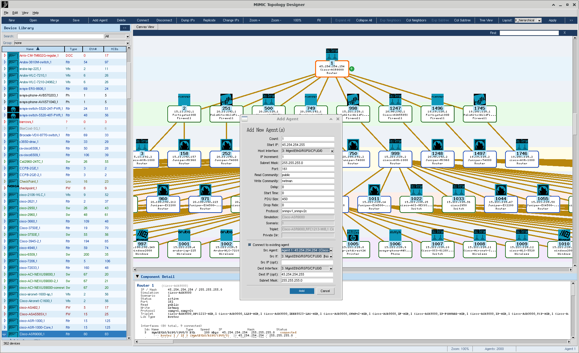
All paths open the same Add Agent dialog, with these fields:

  • Count — How many agents to create in one shot.
  • Start IP — The host IP of the first agent.
  • IP Increment — Step between successive host IPs.
  • Subnet Mask — Subnet mask for all new agents.
  • Port, Read Community, Write Community, Protocol — Standard SNMP agent parameters.
  • Simulation, Scenario — The MIMIC simulation behind the agent. Pre-filled when you drag from the Device Library.
  • Host Interface — Which interface of the simulation carries the host IP. The dropdown is populated from the simulation's MIB.

Figure 2: Add Agent dialog

Figure 2: Add Agent dialog.

Connecting Interfaces

A connection joins two interfaces from two different agents (or, for a self-loop, two interfaces of the same agent). Connections are recorded in the _TOPO_ section of the .cfg file and drive the topology as visualized by NMS tools.

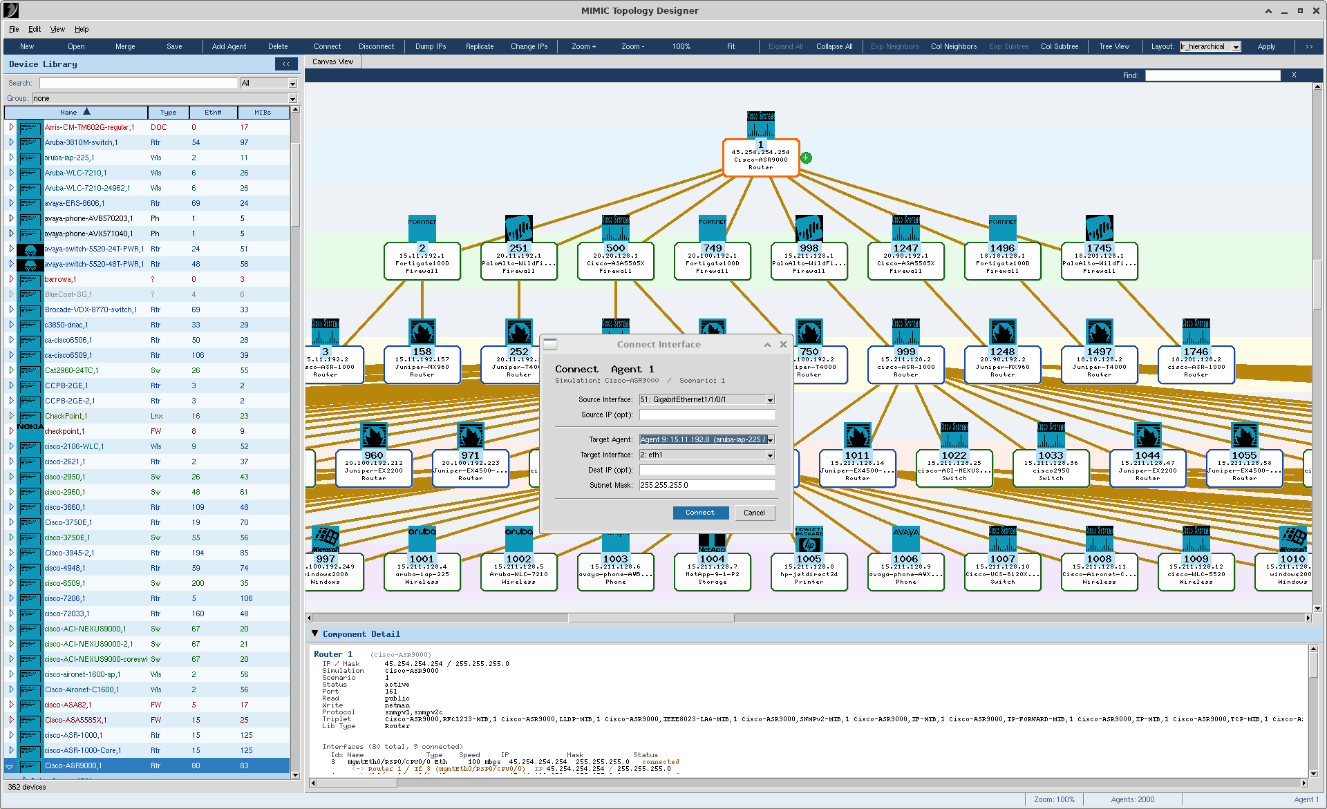
Creating a Connection

  1. Select the source agent (or right-click it and pick Connect Interface).
  2. In the Connect Interface dialog, choose the source interface from the dropdown.
  3. Choose the target agent and target interface.
  4. Optionally set a subnet mask and the IPs at each end.
  5. Click Connect.
Quick Connect: selecting a single agent reveals a small green + badge to its right. Click the badge, then click the target agent on the canvas — the Connect Interface dialog opens with both ends already filled in. See Inline Badges on Agent Nodes for details.

Overriding a Management ([host]) Interface

Each agent's management interface — the one carrying its hostaddr / SNMP binding — appears in the Source Interface and Target Interface combos with a small [host] tag, for example 1: eth0 [host]. You can pick a [host] entry and use it as a real connection endpoint, but the Designer asks you to confirm first because doing so converts that interface from a self-loop into a peer-to-peer link.

  1. In the Connect Interface dialog, select a [host] entry on either side (Source, Target, or both).
  2. Click Connect.
  3. A confirm dialog "Override management interface?" lists each side affected and asks "Override and connect anyway?". The default is No.
  4. Click Yes to proceed. The connection is created and the agent's hostaddr IP is preserved on that interface, so the management binding survives. Click No to leave the topology unchanged.
Note: Overriding a management interface can be undone with Ctrl+Z. Cross-agent overwrite (replacing an already-connected non-host interface with a different peer) is still refused outright — only self-loop overrides are offered for confirmation.

Duplicate-IP Protection

The Designer refuses to assign the same IP address to two different agents or interfaces. If you try to add an agent with a hostaddr that another agent already owns, or rename an interface IP into a conflict, or wire up a connection whose IP collides with an existing assignment, the operation is rejected with "IP X already used by Y". The same protection runs across the Auto Topology Wizard and the merge / replicate paths, so generated topologies cannot silently produce overlapping addresses. The one allowed exception is the same agent reusing its hostaddr as one of its connected interface IPs (the standard MIMIC management-binding pattern).

Removing a Connection

  • Right-click the connection line on the canvas and choose Disconnect.
  • Or, right-click an agent and choose Disconnect Interface. If the agent has multiple links, you can pick one specific connection or disconnect them all.

Figure 3: Connect Interface dialog

Figure 3: Connect Interface dialog.

Editing Agents and Interfaces

To change properties of an existing agent:

  • Double-click it on the canvas, or
  • Right-click it and choose Edit Agent, or
  • Double-click the agent row in the Tree View.

The Edit Agent dialog mirrors the Add Agent dialog with current values pre-populated. You can change the host IP, mask, communities, simulation, scenario, device type, and which interface carries the management IP.

Note: changing the Host Interface moves the management IP from one interface to another and updates the _TOPO_ connection records to match. If this agent was the target of any connection, the source agent's record is updated too.

To edit an individual interface (its IP or connection peer), expand the agent in the Tree View, then double-click the interface row.

Selection

Many operations work on the current selection — Delete, Replicate, Group into Submap, Expand Subtree, and so on. The Designer offers several ways to build a selection:

  • Single click on an agent.
  • Shift + click to add or remove an agent from the selection.
  • Rubber-band: click on empty canvas and drag to draw a selection rectangle.
  • Edit > Select > All / None / Invert.
  • Edit > Select > By Number... — Enter an ID range like 1-5, 42, 100-200.
  • Edit > Select > By IP... — Enter an IP, subnet, or range.

The current selection count and a brief description of the active item are always shown in the status bar at the bottom of the window.

Search and Filter

The Find box (above the canvas) filters the display in real time. Typing in the box matches against:

  • Agent ID (aid)
  • Host IP and subnet mask
  • Interface IPs
  • Simulation and scenario names
  • Device type
  • System description (sysDescr) from the simulation MIB

While a filter is active:

  • Non-matching agents are hidden on the canvas and in the Tree View, but remain in the data model — they are restored as soon as you clear the filter.
  • Submaps containing at least one match show a ★N badge with the match count. Expand the submap to drill down.
  • The status bar shows the count of matching agents, for example "Agents: 3 of 142 ★3".

Press Escape in the Find box or click the X button to clear the filter.

Canvas Layouts

The Designer can automatically arrange agents using several layout algorithms. Pick one from the toolbar's Layout dropdown or from View > Canvas Layout, then click Apply:

  • Grid — Arrange agents in a rectangular grid by agent ID. Useful as a starting point for large topologies.
  • Hierarchical — Top-down multi-level tree, with roots at the top and leaves at the bottom.
  • LR Hierarchical — Left-to-right variant of Hierarchical. This is the default.
  • Circular — Concentric rings by distance from the most-connected node.
  • Star — A central hub with radial spokes. Particularly suitable for output of the Auto Topology Wizard.
  • Force-Directed — Physics simulation with repulsive forces between nodes and attractive forces along edges. Produces visually balanced graphs but can be slow on very large topologies.
  • Spring — A mass-spring variant of force-directed with different parameters.
Tip: after applying an automatic layout you can still drag individual agents by hand to fine-tune their positions. The new positions are preserved on save in the sibling .lay file.
Note: any layout other than Grid repositions every agent. If you have a carefully hand-crafted layout you want to keep, save it first.
Tip: switching between Hierarchical and LR Hierarchical is a pure transpose — every agent's X and Y just swap, so the within-level spacing and any manual nudges you applied are preserved exactly. Switching to or from any other layout family rebuilds the positions from scratch.

When you re-open a saved topology, the Designer figures out which layout family the .lay file represents by looking at the positions themselves (clusters of agents along distinct row or column lines), and sets the toolbar dropdown accordingly. This means a subsequent merge into the topology will place the new agents along the matching cross-flow axis even if the dropdown said something else when you opened the file. Freeform (hand-arranged) .lay files leave the dropdown alone.

Submaps

Submaps let you group related agents into a single collapsible icon so a very large topology stays readable. Submaps can be nested arbitrarily deep.

Creating a Submap

  • Select two or more agents, then Edit > Group Selection into Submap....
  • Right-click an agent and choose Add to Submap > New Submap....
  • Use Edit > New Submap... (or View > Submap Manager > New) and pick members from the dual-list selector.

In the submap dialog you specify:

  • Description — The user-facing name of the submap.
  • Parent — Either (top-level) or an existing submap (nests this submap inside).
  • Color — Outline color of the submap icon. Click Pick... to choose interactively.
  • Members — Move agents between the Available and Selected lists. Each agent is labeled "aid: hostaddr" so you can identify it.

Expanding and Collapsing

  • Double-click a submap icon to expand it (show members) or collapse it (hide members behind the icon).
  • Right-click the icon and choose Expand / Collapse.
  • View > Expand All Submaps / Collapse All Submaps for bulk operations.

Editing and Dissolving

  • Edit Submap... — Change the description, color, or membership.
  • Dissolve Submap — Delete the submap; its members return to the top level. Nested submaps re-parent to the dissolved submap's parent.

The Submap Manager

View > Submap Manager... opens a single dialog listing every submap with its direct member count, transitive member count, and expand / collapse state. From here you can create, edit, or delete submaps without hunting for them on the canvas.

Note: a given agent can belong to at most one submap at a time. If you drag an agent into a different submap (or move it via the Edit dialog) the Designer asks you to confirm before changing its parent.

Auto Topology Wizard

The Auto Topology Wizard generates a multi-level star topology from a few high-level inputs — useful when you want a large topology quickly. Open it from Edit > Auto Topology Wizard... or the Auto Topo toolbar button.

Step 1 — Mode

Choose whether to:

  • Create a brand-new topology, or
  • Load and modify an existing .cfg file (browsed from the scripts/topo/ directory).

Step 2 — Topology Parameters

Specify:

  • Number of devices — The total agent count. Stay within the limits of your MIMIC license keys (Help > About MIMIC...).
  • End-system devices — Per spoke; the number of leaf nodes per second-most-outer device.
  • Seed IP and Seed Mask — The IP of the root device of the star.
  • Device seed ID — The first agent ID in the generated topology.
  • Subnet List — One or more ip/mask entries the generator pulls IP addresses from. If you leave this list empty the Designer silently uses the seed's own subnet (seed_ip & mask), starting allocation just past the seed's address so the children never collide with the seed.
  • Topology Levels — A list of levels with the device count and the device types at each level. Double-click a level row to edit it.

You can also drag devices from the Device Library directly onto a level band to assign them.

How Many Levels Do You Need?

The generator treats the last level as the end-system layer. Every non-end-layer device uses all of its ethernet interfaces — one for the up-link to its parent and the rest as down-links to its children (the seed uses one iface for its own loopback and the rest for L2 children). The maximum device count you can fit is:

1 + Σ (product of MAX(eth-1) across levels)

where eth is the largest ethernet- interface count among the device types you assigned to each level (the DFS rotates types and picks the best-fanout available). Adding more device types to a level raises the ceiling — the strongest device wins.

If you ask for more devices than the tree can hold, the Designer's pre-flight check refuses to run generation and shows a dialog with the exact maximum and four suggested fixes: reduce Total Devices, add another topology level, pick devices with more ethernet interfaces at inner levels, or increase End Systems.

Generation

When you click Generate the Designer creates the agents, wires up the star connections, and lays the result out on the canvas. You can then continue editing manually (renumber IPs, add submaps, change the layout, etc.) before saving.

If generation hits an unavoidable IP conflict (e.g., a hand-typed subnet that overlaps with the seed's IP), the Designer rolls back the partial generation via Ctrl+Z and pops a dialog explaining which IP collided. The canvas is never left in a half-generated state.

Large Topologies (Threshold Prompt)

Generation renders on the canvas by default. If you ask for more agents than the render threshold (default 10000), the Designer pops a three-way prompt before committing to the render:

  • Yes — Generate and render on the canvas (may take a while for very large topologies).
  • No — Generate and save as a .cfg file only; the canvas stays empty. The Designer walks you through the Save dialog immediately, then clears the in-memory model so subsequent File > Save operations don't accidentally re-write the huge topology.
  • Cancel — Return to the wizard with no changes.

You can override the threshold by editing config/topodesigner.cfg (in your MIMIC private directory or the install-shared config folder) — see the Runtime Configuration File section below. Non-integer or negative values are ignored; the built-in default (10000) applies.

Generation of any size never leaves the topology in a partially-connected state — if the DFS can't attach every requested agent, the Designer throws, rolls back via Ctrl+Z, and shows an error dialog pointing at the diagnostic log ($MIMIC_TMPDIR/auto_topo_diag.log) that lists the exact interface-exhaustion events. This is the "stop creating if it doesn't fit" runtime backstop — mirrors the old Auto Topology Wizard's Topology was not created successfully dialog.

Replicate Topology

Replicate creates one or more copies of the current topology with fresh IP subnets, useful for scaling up a small reference topology into a much larger one. Open it from Edit > Replicate Topology or the toolbar.

Dialog Fields

  • Copies — Number of replicas (1-99). The total agent count updates live as you change this.
  • All — A single base IP/mask (e.g., 10.11.1.1/24) that replaces every detected subnet per copy. When set, the per-subnet rows below are disabled. Clearing this re-enables per-subnet mapping.
  • Subnet Mapping — One row per detected /24 in the current topology. Type a new base into a row to control how that subnet is replicated; leave a row blank to use the default auto-increment of the third octet (10.0 → 10.1 → 10.2…).

The replicated copies preserve interface IDs, connection topology, and submap membership. Click Replicate to commit.

Note: Replicate appends the new copies to the existing topology; the original agents are not removed. The new copies are placed in their own space, along the cross-flow axis of your current layout: to the right for top-down hierarchical, circular, star, and force layouts; below for LR hierarchical and grid. Repeated replication never overlaps, since each new copy starts past the far edge of all prior content.

Change IPs

Change IPs remaps every IP in the current topology to a new subnet, without creating any new agents. The dialog is similar to Replicate but has no "Copies" field.

Use this when you load a sample topology and want to move it into your own IP space before saving.

All — pack into one subnet. Typing an IP/Mask like 10.11.1.1/24 into the All field greys out the per-subnet rows and packs every unique IP in the topology into that subnet sequentially, starting at the IP you typed: the first source IP becomes 10.11.1.1, the second 10.11.1.2, and so on. Hostaddrs get the low host octets first, interface IPs follow. If the topology has more unique IPs than the chosen subnet can hold, the Designer refuses with a clear error suggesting a larger mask (/23, /22, …) or a lower starting IP. Clear All to re-enable the per-row entries.

Manual entry. With All empty, edit individual rows. If you type the same target subnet into multiple rows, clicking Change IPs pops up an IP collision dialog listing every duplicate new IP with its owners (for example, 10.1.0.1 ← agent 3, agent 7). Nothing is committed; the Undo stack is untouched.

Same-agent allowance. Every agent's hostaddr also lives on one of its own interfaces (the host self-loop). The collision check is aware of this and does not flag the hostaddr-on-own-interface pattern — only IPs claimed by two different agents count as a collision.

Save-time safety net. If anything else introduces a cross-agent duplicate IP into the topology, File > Save refuses to write and pops an error pointing at the conflicting agents — so a corrupted cfg can never round-trip through the Designer.

Dump IPs

The Dump IPs dialog (Edit > Dump IPs) shows and exports the full IP inventory of the current topology in four tabs:

  1. Host IP List — One hostaddr per line, sorted.
  2. Host IP Ranges — Hostaddrs grouped by /24 with consecutive IPs collapsed into ranges (e.g., 10.0.0.1-10.0.0.10).
  3. Used IP List — All IPs in use (hostaddrs plus interface IPs), sorted.
  4. Used IP Ranges — Used IPs grouped by /24, with ranges.

Each tab is also written to a file in $MIMIC_TMPDIR (or /tmp if that is not set):

  • hostiplist
  • hostiprange
  • usediplist
  • usediprange

Click Copy to Clipboard on any tab to copy that view to the clipboard.

Undo and Redo

Almost every topology-changing operation in the Designer can be undone with Ctrl+Z and redone with Ctrl+Y:

  • Adding, editing, or deleting an agent.
  • Connecting or disconnecting an interface.
  • Creating, editing, dissolving, or modifying members of a submap.
  • Dragging an agent to a new position.
  • Applying a canvas layout.
  • Replicate Topology and Change IPs.

The Designer keeps up to 20 undo levels. Pure view changes — zoom, pan, expand / collapse, and search filter changes — are not tracked in the undo stack because they do not modify the topology.

Saving and Loading

The Designer reads and writes the standard MIMIC agent configuration format. A complete topology consists of up to three sibling files sharing the same base name:

Extension Purpose Required
.cfg Agent definitions and the _TOPO_ block of connections. This is the file that MIMIC loads to run a simulation. Yes
.lay Canvas positions for each agent, so the Designer reopens the topology with the same visual layout you saved. No (auto-laid-out if missing)
.map Submap definitions (names, members, colors, positions). Shared with MIMICView. No (only if you defined submaps)

All three files are read and written together by Open and Save. You never need to manage them individually.

Save Dialog

The Save dialog lists recent .cfg files from $MIMIC_TMPDIR/config/agents and $MIMIC_DIR/config/agents. You can click a row to overwrite an existing file, or type a new file name in the entry box at the bottom.

The Designer also auto-saves your work to a recovery file at regular intervals so an unexpected exit will not lose more than a few changes.

Deleting a Config File

The Open, Merge, and Save dialogs each have a Delete button on the left of the button row. Select a file in the list to enable it; click Delete and confirm the warning ("File will be deleted permanently.") to remove the .cfg and its sibling .lay + .map files together.

Files under the shared location (blue in the Location column) are read-only; the Delete button stays disabled when you select one. Only your private config/agents/ files can be deleted this way — the shared install stays intact. The same button is present in the Auto Topology Wizard's Load-config and Save-config browsers (which manage scripts/topo/ configs).

Save Progress on Large Topologies

Saving 10k+ agents shows a determinate progress bar that ticks the number of agents written. The bar advances 0-100% during the write loop; if the pre-write consistency check spots an IP mismatch between the model and the live IP registry, the save aborts with a specific error and no partial file is left on disk.

Right-Click Context Menus

The right mouse button is overloaded to give you fast access to whatever is most relevant for the item under the cursor.

Right-click on an Agent

  • Edit Agent <id> / Delete Agent
  • Show Connections — List all of the agent's interfaces and their peers.
  • Connect Interface / Disconnect Interface
  • Expand Neighbors / Collapse Neighbors
  • Expand Subtree / Collapse Subtree
  • Add to Submap > submenu — New Submap..., or the name of any existing submap.
  • Add Subtree to Submap (N agents) — Group the agent and every downstream agent into a submap.
  • Remove from Submap 'name' — Lift the agent back to the top level.
  • Collapse Submap 'name' — Collapse the nearest containing submap.

Right-click on a Submap Icon

  • Expand / Collapse
  • Edit Submap...
  • Add Sub-Submap...
  • Dissolve Submap

Right-click on a Connection Line

  • Show Details — Open the Component Detail panel with the link's properties.
  • Disconnect

Right-click on Empty Canvas

  • Add Agent Here — Add an agent at the click location.
  • New Submap...
  • Expand All Submaps / Collapse All Submaps
  • Toggle Submap > submenu — Expand or collapse a specific submap.

Right-click in the Tree View

Mirrors the canvas menus for the corresponding agent, interface, or submap. Right-click the Agents header for bulk actions (New Submap, Expand All, Collapse All).

Keyboard Shortcuts

Shortcut Action
Ctrl+NNew topology
Ctrl+OOpen .cfg file
Ctrl+SSave topology
Ctrl+QExit the Designer
Ctrl+ZUndo last topology change
Ctrl+YRedo
Ctrl+=Zoom in
Ctrl+-Zoom out
Ctrl+0Reset zoom to 100%
Ctrl+FFit all visible nodes in window
Ctrl+DToggle Device Library panel
DeleteDelete selected agent(s)
EscapeClear selection / close Find box
Mouse wheelZoom canvas
Middle-click + dragPan canvas
Shift + clickAdd/remove agent from selection
Click + drag on empty canvasRubber-band select
Double-click agentEdit agent
Double-click submapExpand / collapse submap

Runtime Configuration File

The Topology Designer reads a simple key = value file named topodesigner.cfg at startup. Two copies are supported:

  • Shared: <MIMIC install>/config/topodesigner.cfg — defaults documented for every configurable.
  • Private: $MIMIC_PRIV_DIR/config/topodesigner.cfg — your per-workspace overrides. Any key here wins over the shared copy.

Format: one key per line, # comments supported, blank lines ignored. Environment variables are no longer consulted — this file is the only override path. You must close and reopen the Designer to pick up a change.

Recognized keys:

KeyDefaultPurpose
large_threshold 10000 Auto Topology Wizard prompts Yes/No/Cancel when the requested device total exceeds this value. Set to 0 to always ask; higher values suppress the prompt for larger topologies.
ascii_glyphs 0 Set to 1 to force ASCII toolbar and fold-triangle glyphs on all platforms. Default auto-detects: Unicode when the system font can render the codepoints, ASCII otherwise.
bitmap_bg_color #90d0c0 Backdrop color behind device-library and canvas node vendor bitmaps.
edge_color #b8860b Unselected, non-bundled connecting line color.
selected_edge_color #ff6600 Highlight color for the currently selected edge.
bundled_edge_color #7a5a00 Color for a bundle line (multiple source-interfaces collapsed into one).
selected_node_border #ff6600 Border ring color for a selected agent frame.
unselected_node_border (empty) If set, overrides both Router (#1144bb) and Non-Router (#116611) type-color borders with a single uniform color. Leave blank to keep the type distinction. Deleted-agent grey stays fixed.
hidden_badge_color #ff9933 Fill for the orange >> pill that appears on a node with collapsed downstream neighbors.
hidden_badge_outline #cc6600 Outline color for the same pill. Text stays white for contrast.

Any value that is not a valid Tk color (e.g. #00A36 — five hex digits) is silently rejected at load; the built-in default is used instead. Named colors like white, navy, or lightblue are accepted.

Sample topodesigner.cfg:

# Topology Designer configuration
large_threshold = 25000
ascii_glyphs = 0
bitmap_bg_color = white
edge_color = #444444
selected_edge_color = red

Tips and Best Practices

  • Start with the Auto Topology Wizard for a quick base layout, then customize manually. It is much faster than placing each device by hand.
  • Use submaps aggressively on topologies of more than ~100 agents. A collapsed submap looks like a single node but encapsulates an entire subnetwork.
  • Drag from the Device Library instead of typing in the Add Agent dialog — you get the right simulation, scenario, and interface set with no typing.
  • Hierarchical or LR Hierarchical are the best general-purpose layouts. Force-directed is excellent for showing graph structure but slows down on very large topologies.
  • Save early, save often. The Designer auto-saves a recovery copy, but explicit saves into your own .cfg file are still important.
  • Use Replicate to scale a small reference topology into a much larger one rather than hand-building thousands of agents.
  • Filter aggressively: the Find box matches against agent ID, IPs, simulation name, device type, and system description. Combined with submaps it lets you find any device in seconds, even in a 10,000-agent topology.
  • Tree View is invaluable when the canvas is too dense to click precisely.
  • Right-click first. The context menus expose options that are not in the menu bar, and they always operate on the item under the cursor — no separate selection step.